Assume a source of power PS in the look direction, hereafter referred to as the signal source, with mS(t) denoting its modulating function. The signal induced on the lth element due to this source only is given by
(2.3) |
Thus, in vector notation, using steering vector to denote relevant phases, the array signal vector due to look direction signal becomes
(2.4) |
The output of the processor is obtained by taking the inner product of weight vector wc with the signal vector x(t) as in (4). Thus, the output of the processor is given by
(2.5) |
Substituting from (2.1) and (2.4), and noting that (S0)H*S0 = L, the output becomes
(2.6) |
Thus, the output of the conventional processor is the same as the signal induced on an element positioned at the reference element. Next, look at its mean out power. As there is only the signal source present, the mean output power of the processor is the mean signal power given by (16), that is,
 |
(2.7) |
Since
(2.8) |
substituting from (2.1), (2.8) in (2.7),
(2.9) |
Thus, the mean output power of the conventional processor steered in the look direction is equal to the power of the source in the look direction. The process is similar to mechanically steering the array in the look direction except that it is done electronically by adjusting the phases. This is also referred to as electronic steering, and phase shifters are used to adjust the required phases. It should be noted that the aperture of an electronically steered array is different from that of the mechanically steered array.
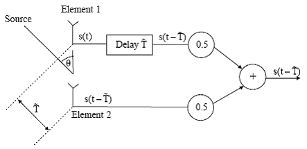
The concept of delay-and-sum beamformer can be further understood with the help of Figure 4, which shows an array with two elements separated by distance d. Assume thata plane wave arriving from direction θ induces voltage s(t) on the first element.
As the wave arrives at the second element T seconds later, with
(2.10) |
the induced voltage on the second element equals s(t − T ). If the signal induced at Element 1 is delayed by time T, the signal after the delay is s(t − T ) and no delay is provided at Element 2, then both voltage wave forms are the same. The output of the processor is the sum of the two signals s(t −T). A scaling of each wave form by 0.5 provides the gain in direction θ equal to unity.

Figure 4: Delay-and-sum beamformer.
Back to conventional beamformer.
Conventional beamformer in the presence of directional interference is discussed here.
Conventional beamformer in the presence of an environment consisting of uncorrelated noise is discussed here.
Signal to noise ratio (SNR) of a conventional beamformer is discussed here.
Back To Contents.