Introduction Of Smart Antenna Mathematically
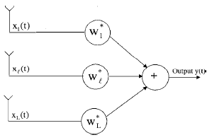
Consider the antenna array system consisting of L antenna elements shown in Figure 1, where signals from each element are multiplied by a complex weight and summed to form the array output. The figure does not show components such as preamplifiers, bandpass filters, and so on. It follows from the figure that an expression for the array output is given
 |
(1) |
where * denotes the complex conjugate. The conjugate of complex weights is used to simplify the mathematical notation. Denoting the weights of the array system using vector notation as
(2) |
and signals induced on all elements as
(3) |
the output of the array system becomes
(4)
|
 |
Figure 1: antenna array system
where superscript T and H, respectively, denote transposition and the complex conjugate transposition of a vector or matrix. w and x(t) are referred to as the weight vector and the signal vector, respectively. Note that to obtain the array output, you need to multiply the signals induced on all elements with the corresponding weights. In vector notation, this operation is carried out by taking the inner product of the weight vector with the signal vector.
The output power of the array at any time t is given by the magnitude square of the array output, that is,
 |
(5) |
Substituting for y(t) from (4), the output power becomes
(6) |
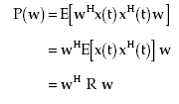
If the components of x(t) can be modeled as zero-mean stationary processes, then for a given w the mean output power of the array system is obtained by taking conditional expectation over x(t)
 |
(7) |
where E[.] denotes the expectation operator and R is the array correlation matrix defined by
(8)
|
Elements of this matrix denote the correlation between various elements. For example, Rij denotes the correlation between the ith and the jth element of the array.
Consider that there is a desired signal source in the presence of unwanted interference and random noise. The random noise includes both background and electronic noise. Let xS(t), xI(t), and n(t), respectively, denote the signal vector due to the desired signal source, unwanted interference, and random noise. The components of signal, interference, and random noise in the output yS(t), yI(t), and yn(t) are then obtained by taking the inner product of the weight vector with xS(t), xI(t), and n(t). These are given by
(9) |
|
(10) |
|
(11) |
Define the array correlation matrices due to the signal source, unwanted interference, and random noise, respectively, as
(12) |
|
(13) |
|
(14) |
Note that R is the sum of these three matrices, that is,
(15) |
Let PS, PI and Pn denote the mean output power due to the signal source, unwanted interference, and random noise, respectively. Following (7), these are given by
(16) |
|
(17) |
|
(18) |
Let PN denote the mean power at the output of the array contributed by random noise and unwanted interference, that is,
(19) |
We refer to PN as the mean noise power at the output of the array system. Note that the noise here includes random noise and contributions from all sources other than the desired signal. In some sources, this is also referred to as noise plus interference. Substituting from (17) and (18) in (19),
 |
(20) |
Let RN denote the noise array correlation matrix, that is,
(21) |
Then PN, the mean noise power at the output of the system can be expressed in terms of weight vector and RN as
(22) |
Let the output signal-to-noise ratio (SNR), sometimes also referred to as the signal to interference plus noise ratio (SINR), be defined as the ratio of the mean output signal power to the mean output noise power at the output of the array system, that is,
(23) |
Substituting from (16) and (22) in (23), it follows that
(24) |
The weights of the array system determine system performance. The selection process of these weights depends on the application and leads to various types of beamforming schemes.
For more information about antenna array you can click 1, 2, 3, 4, 5, 6.
For more information about phased array you can click 1, 2.
| In the | next page | signal model a is discussed . |
Back To Contents.