PIC with Orthogonal
Interference Beamformer
| Let the interference beam be formed using the beamforming weights | |
| (6.62) | |
| where Uo is a complex vector such that | |
| (6.63) |
The constraint specified by (6.63) ensures that the interference beam has a null in the signal direction. Thus, the interference beam does not contain any signal and the PIC using the orthogonal interference beamformer (OIB) does not suppress the signal. Note that the vector Uo may be a steering vector. This case corresponds to the parameter ρ taking on a value of unity.
Various expressions for optimal PIC using the OIB are now presented. It is assumed that the interference beam of the PIC using the OIB does not have a null in the interference direction. If the interference beam had a null in the interference direction, then there would be no interference present in this beam and no reduction in the interference from the signal beam would result by forming the PIC output by subtracting the weighted output of the interference beam from the signal beam.
From (6.48), (6.50) and (6.62), it follows that the optimal weight wˆo of the PIC using the OIB is given by
| (6.64) | |
| Substituting for R in (6.64), one obtains, after manipulation, | |
| (6.65) | |
| where | |
| (6.66) | |
| and | |
| (6.67) | |
| Note that γo, as defined by (6.67), is a positive real scalar, with | |
| (6.68) |
and represents the normalized power response of the interference beam in the direction of the interference.
The expressions for the signal power, the residual interference power, the uncorrelated noise power, and total noise power at the output of the optimal PIC using the OIB are, respectively, obtained by substituting for R equals RS, RI, Rn and RN, and w = wˆo in (6.46). These are given by
| (6.69) | |
 |
(6.70) |
 |
(6.71) |
| and | |
 |
(6.72) |
| From expressions (6.69) to (6.72), the following observations can be made: |
1. The optimal PIC using the OIB does not suppress the signal. This is because there is no leakage of the signal into the interference beam.
2. The residual interference power of the optimal PIC using the OIB depends on PI/σn^2 . For a given array geometry and noise environment, the normalized residual interference power PI(wo)/PI decreases as PI/σn^2 increases. In a noise environment with a very high PI/σn^2 , the residual interference power of the optimal PIC using the OIB becomes very small. In the limit, as
 |
(6.73) |
| which lead to full cancelation of the interference (see Equation 6.70). On the other hand, as | |
| (6.74) | |
| and no cancelation of the interference takes place. |
3. The uncorrelated noise power at the output of the PIC is more than the uncorrelated noise power at the output of the signal beam. This follows from (6.71). The RHS of (6.71) consists of two terms. The first term is the same as the uncorrelated noise power at the output of the signal beam and the second term is proportional to the uncorrelated noise power at the output of the signal beam; the proportionality constant in the square brackets depends on the PI/σn^2 . As PI/σn^2 increases, the quantity in the square brackets increases. This is due to the fact that wˆo increases as PI/σn^2 increases. In the limit, the maximum increase in the uncorrelated noise power caused by the optimal PIC using the OIB is σn^2 /L (1 – ρ)/γo.
4. The total noise power PN(wo) at the output of the optimal PIC using the OIB does not depend on the signal power. It is proportional to the uncorrelated noise power, at the output of the signal beam and decreases as P1/σn^2 decreases. The uncorrelated noise dominates the total noise at the output of the optimal PIC.
Now the output SNR of the optimal PIC using the OIB is examined. Let this ratio be denoted by SNR(wo). It follows from (6.69) and (6.72) that
 |
(6.75) |
Thus, the output SNR of the optimal PIC using the OIB is proportional to the number of elements and PS/σn^2 ; and depends on PI/σn^2. As
 |
(6.76) |
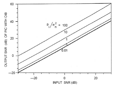
Figure 13 shows SNR(wo) vs. input SNR for various PI/σn^2 . The array geometry and noise environment used for this example is the same as that used for Figure 12. The interference beam is formed using the steering vector in the endfire direction. The parameter γo for this case is 0.17. From Figure 13, for a given input SNR the output SNR increases as PI/σn^2 increases.

Figure 13 : Output SNR of the PIC using OIB vs. input SNR for a ten-element linear array, θ0 = 90°, PI = 1, θI = 30°.
PIC with Conventional Interference Beamformer is discussed here.
PIC with Improved Interference Beamformer is discussed here.
Back to PIC.
Back To Contents .