A structure of the generalized side-lobe canceler is shown in Figure 10. The array is presteered by delaying received signals on all antennas such that the component of the received signal on all elements arriving from the look direction is in phase after presteering delays. Let αl, l = 1, 2, …, L denote the phase delays to steer the array in the look direction. These are given by
| (6.29) |
(6.30) |
|
| This along with (1.9) imply that x′(t) are related to x(t) by | |
| (6.31) | |
| where Φ0 is a diagonal matrix defined as | |
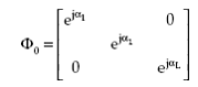 |
(6.32) |
Note that Φ0 satisfies the relation, (Φ0)H*S0 = 1, where 1 is a vector of ones.
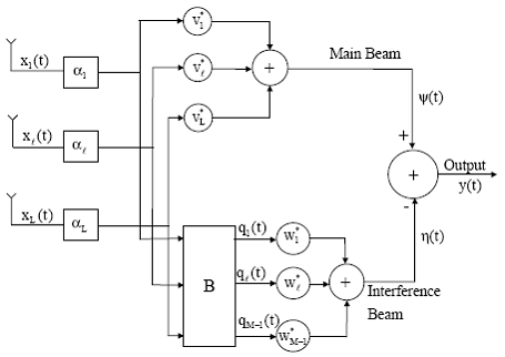
Figure 10 : Generalized side-lobe canceler structure.
These signals are used to form the main beam as well as M – 1 interference beams. The main beam is formed using fixed weights on all channels. These weights are selected to be of equal to 1/L so that a unity response is maintained in the look direction. Let these be denoted by an L-dimensional vector V given by
| (6.33) |
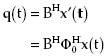 |
(6.34) |
| where matrix B has rank M – 1 and satisfies | |
| (6.35) |
| (6.33) | |
 |
(6.37) |
| and | |
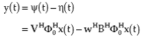 |
(6.38) |
 |
(6.39) |
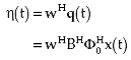
| Where | |
| (6.40) |
| (6.41) | |
| The expression for the mean output noise power of the optimal GSC then becomes | |
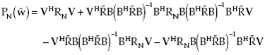 |
(6.42) |
and the output SNR is given by (6.28). For more information about Generalized Side-Lobe Canceler you can click here. In the next page Postbeamformer Interference Canceler is discussed. Back To Contents . |