1.Signal model:
In this section, a signal model is described and expressions for the signal vector and the array correlation matrix required for the understanding of various beamforming schemes are written. Assume that the array is located in the far field of directional sources. Thus, as far as the array is concerned, the directional signal incident on the array can be considered as a plane wave front. Also assume that the plane wave propagates in a homogeneous media and that the array consists of identical distortion-free omnidirectional elements. Thus, for the ideal case of nondispersive propagation and distortion free elements, the effect of propagation from a source to an element is a pure time delay.
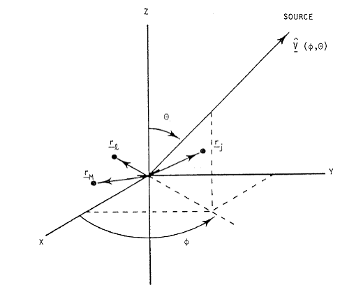
Let the origin of the coordinate system be taken as the time reference as shown in Figure 2 Thus, the time taken by a plane wave arriving from the kth source in direction (Φk,θk) and measured from the lth element to the origin is given by
 |
(1.1) |
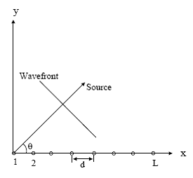
where rl is the position vector of the lth element, v(Φk,θk) is the unit vector in direction (Φk,θk), c is the speed of propagation of the plane wave front, and the dot represents the dot product. For a linear array of equispaced elements with element spacing d,aligned with the x-axis such that the first element is situated at the origin as shown in Figure 3, it becomes
(1.2) |

Figure 2: coordinate system

Figure 3:linear array with element spacing d
Note that when the kth source is broadside to the array, θk = 90. It follows from (1.2) that for this case, τ1(θk) = 0 for all l. Thus, the wave front arrives at all the elements of the array at the same time and signals induced on all the elements due to this source are identical. For θk = 0, the wave front arrives at the lth element before it arrives at the origin, and the signal induced on the lth element leads to that induced on an element at the origin. The time delay given by (1.2) is
(1.3) |
On the other hand, for θk = 180, the time delay is given by
(1.4) |
The negative sign is due to the definition of τl. It is the time taken by the plane wave from the lth element to the origin. The negative sign indicates that the wave front arrives at the origin before it arrives at the lth element, and the signal induced on the lth element lags behind that induced on an element at the origin.
The signal induced on the reference element (an element at the origin) due to the kth source is normally expressed in complex notation as
(1.5) |
with mk(t) denoting the complex modulating function and f0 denoting the carrier frequency. In general, the modulating function is normally modeled as a complex low-pass process with zero mean and variance equal to the source power pk as measured at the reference element. Assuming that the wave front on the lth elements arrives τl(Φk,θk) seconds before it arrives at the reference element, the signal induced on the lth element due to the kth source can be expressed as
(1.6) |
The expression is based upon the narrowband assumption for array signal processing, which assumes that the bandwidth of the signal is narrow enough and that the array dimensions are small enough for the modulating function to stay almost constant during τl(Φk,θk) seconds, that is, the approximation mk(t) = mk(t + τl(Φk,θk)) holds
Assume that there are M directional sources present. Let xl
 |
(1.7) |
where nl(t) is random noise component on the lth element, which includes background noise and electronic noise generated in the lth channel. It is assumed to be temporally white with zero mean and variance equal to бn^2 . Furthermore, it is assumed to be uncorrelated with directional sources, that is,
(1.8) |
The noise on different elements is also assumed to be uncorrelated, that is,
 |
(1.9) |
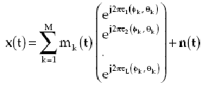
It should be noted that if the elements were not omnidirectional, then the signal induced on each element due to a source is scaled by an amount equal to the response of the element under consideration in the direction of the source.Substituting from (1.9) in (3), the signal vector becomes
 |
(1.10) |
where the carrier term exp(j2πf0t) has been dropped for the ease of notation as it plays no role in subsequent treatment and
 |
(1.11) |
For more information about linear array you can click here.
For more information about antenna theory you can click here.
In the next page steering vector is introduced.
Back To Contents.