Home > Spectrum Managment > Spectrum Sensing > Detecting Primary Receivers
Recently there has been great interest in re-evaluating the spectrum usage policy in the US.This stems from the fact that studies have shown that spectrum in the United States is vastly underutilized . One way to increase the utilization of spectrum is by building smarter radios that can detect temporal and spatial “holes” in the spectrum.A large technical hurdle to overcome is the design of a CR that could predict the interference it would cause on nearby users. The FCC calls this the “interference temperature”. Guaranteeing that the interference temperature at a primary receiver will be below a given threshold is very difficult. A technical challenge to overcome involves reducing the uncertainty in the primary receiver location. Recent work on the subject has looked at the detection of weak signals from primary transmitters where it was shown that the problem becomes very difficult when there is uncertainty in the receiver noise variance.In this section suggest the use of a pilot tone from the primary transmitter to help improve detectabilityIn [31, 32] the authors tacitly assume that the locations of the primary receivers are unknown. This leads to the CR needing to rely on using possibly weak primary transmitter signals to make a decision. In [30], the authors show that detectability of weak signals could be significantly improved by having cooperation among the CRs. This work is driven by the question: “How valid is the passive primary receiver assumption?” Specifically, we explore the possibility of detecting primary receivers by exploiting the local oscillator (LO) leakage power emitted by the RF front end of primary receivers. It is widely believed that LO leakage detection is used by the British Broadcasting Corporation to find TV license fee evaders . One aim of this paper is to verify the feasibility of LO detection. Detection of LO leakage is described in more detail in next. This leads to the possibility of reliably locating the primary receivers and using this information to guarantee that a CR will not interfere with primary receivers. By using this additional information we describe a novel cognitive radio system architecture consisting of low cost sensor nodes placed in close proximity to the primary receivers.
DETECTING LO LEAKAGE
Modern day radio receivers are based to a large extent on the superheterodyne receiver architecture invented by Edwin Armstrong in 1918. This architecture is shown in Figure 1.
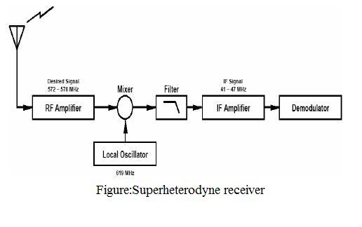
The
architecture has been popular since it allows the RF signal to be
converted down to a fixed lower intermediate frequency (IF),
replacing a low Q tunable RF filter with a low-cost high-Q IF
filter. In order to down-convert an RF band to IF, a local
oscillator (LO) is used. This local oscillator is tuned to afrequency such that when mixed with the incoming RF signal,
the desired RF band is down-converted to the fixed IF band. In
all of these receivers, there is inevitable reverse leakage, and
therefore some of the local oscillator power actually couples
back through the input port and radiates out of the antenna .
In a direct conversion architecture, where the RF is converted
directly down to baseband, the LO frequency will fall within
the band of interest. The LO leakage radiation will then mix
back into the receiver and cause a DC offset to be added to the
signal of interest. This problem is called “self mixing” and is
also solved by using an IF. In most television receivers, the LO
frequency is set to 41MHz above the channel of interest.
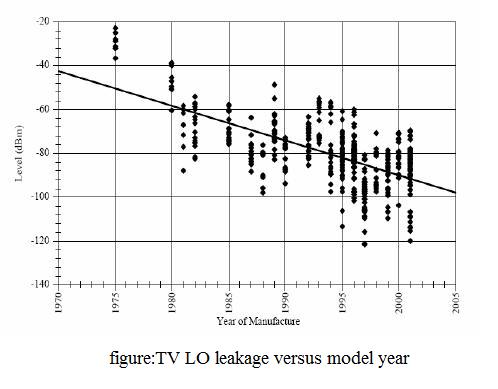
Over the years, improvements have been made to receiver
architectures, resulting in reduced LO leakage power. Figure 2
shows the leakage power of television receivers versus model
year. Detecting this leakage power directly with a CR would be
impractical for two reasons.
Firstly, it would be difficult for the
receive circuitry of the CR to detect the LO leakage over larger
distances. From the calculations shown on the next page, it can
be shown that a distance of 20m, it would take on the order of
seconds to detect the LO leakage with a high probability. For a
practical system, the detection would need to be made on the
order of milliseconds at worst. The second reason that it would
be impractical to detect the LO leakage directly is that the LO
leakage power is very variable, depending on the receiver
model and year. If the CR used this variable power level to
estimate proximity to the primary receiver, there would be too
much error introduced by this variability. We propose to build
tiny, low cost sensor nodes that would be mounted close to the
primary receivers. The node would first detect the LO leakage
to determine which channel the receiver was tuned to.
Several detection schemes exist to detect low energy
signals. Regardless of the detection scheme, the front-end
architecture of the node will be the same. It would consist of an
RF amplifier, filter, and a bank of local oscillators each tuned
such that the desired incoming LO leakage signal will fall into
a fixed IF band. After the IF filter, the signal would be sent to
the detection circuitry. One detector would be implemented for
each channel that the node is supervising. This architecture is
shown in Figure 3.
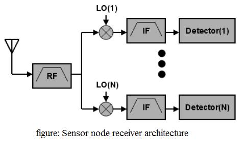
The input into the detector is the desireddown-converted LO leakage signal in addition to additive Gaussian noise. The noise power will be directly proportional to the IF filter bandwidth. Consequently, the IF bandwidth should be kept as narrow as possible. However, it must be wide enough to account for uncertainty in the LO leakage frequency. We first consider the case where each detector is a matched filter. This is the optimal detector to use but requires synchronization. The detector is shown in Figure 5. In the diagram v(t) represents the down-converted LO leakage signal in addition to additive Gaussian noise, n(t). Each detector takes v(t) as an input and correlates it with a sinusoid with frequency corresponding to the LO frequency of one of the N channels, si(t). Since this is a coherent detector, phase synchronization is critical. A Phase Locked Loop (PLL) can be used to match the phase of si(t) to v(t). In many broadcast signals such as television, a pilot carrier is transmitted to aid in phase synchronization. For the case of television broadcast, we would need one detector for each of the channels broadcast. An error occurs when one or more of the detectors determines that an LO signal is not present when one actually is. The converse case, where we detect a LO signal, when one is actually not present is not as important and can be assigned a lower probability.For simplicity, the following analysis assigns equal probabilities to both cases. For a coherent detector and White Gaussian noise statistics, the probability of error from elementary communication theory is:
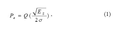
where Es is the energy in the LO signal, σ2 is the receiver noise power, and Q(x) = 1 – F(x), where F(x) is the standard normal distribution function. Let the transmitted LO power be denoted by PT and the received LO power at the sensor node be denoted by PR. For line of sight propagation, it is reasonable to use the free space path loss equation given by:
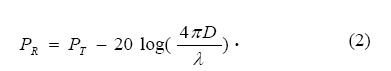
Where D is the distance between transmitter and receiver and λ is the wavelength of the RF radiation. The above path loss equation is simplified in that we are ignoring the antenna gains. We also have that the received LO power is related to the received LO energy by:
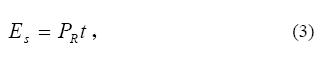
where t is the receiver integration time. For an ideal receiver, the noise power is given by:
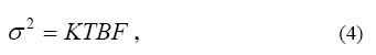
where K is Boltzmann’s constant, T is the temperature, B is the receiver bandwidth and F is the noise factor. To achieve acceptable performance the probability of error and integration time must be kept small.
SYSTEM ARCHITECTURE
When a sensor node detects the presence of a LO, it must notify any CR in the region of the channel usage by means of a control channel. For example, the control channel can use part of the unlicensed spectrum from 420MHz to 450 MHz. To simplify the system, the sensor node can transmit a pilot tone to indicate which channel is used. Different frequency tones would be used to indicate different channels. One problem with this approach is that the CR could be confused if two nearby sensor nodes transmit the same frequency pilot tone. Since the CR would receive a stronger signal at that frequency, it would assume that the primary receiver is much closer than it actually was. As a result, the CR would be more limited in its region of operation. To decrease the magnitude of this problem, we can randomly assign pilot tones to different sensor nodes. The number of possible frequencies the sensor node would use per channel would depend on the bandwidth available on the control channel. This scheme would greatly decrease the probability that several sensor nodes within range of the CR are using the same pilot tone frequency. This random assignment could be hard-wired when the nodes are manufactured.The sensor node is designed to transmit at a fixed power level. This level is chosen such that the cognitive radio will be able to detect the pilot tone if it is within interference range of the primary receiver. This assumes that the principle of reciprocity holds. When the principle holds, the attenuation of the CR’s transmit signal received at the sensor node will be the same as the attenuation of the sensor node’s transmit signal received at the cognitive radio. This means that if the sensor node transmit signal goes through a multipath and shadowing environment to reach the CR, then the CR’s transmit signal will also go through the same environment to reach the sensor node.Reciprocity will not hold exactly, so an additional power margin must be added to the sensor node transmit signal to account for this. To combat the effects of frequency selective fading, the CR could transmit multiple pilot tones at different frequencies to indicate that a channel is used. The chances of all tones being in a fade would thus be dramatically decreased. If the CR finds that a channel is available, it first coordinates among the other cognitive radios on a mechanism to share the spectrum using a suitable MAC protocol. Once a channel is found, it can begin transmitting. The CR will then check periodically if the channel that it is using becomes invalid. When the CR detects that its channel is unavailable, it will stop transmitting immediately and check if another channel is available. The CR must stop transmitting in a small enough time period so that the interference caused to the primary receiver is negligible. The CR will maintain an up to date list of unused channels so that it can quickly hop to an unused band when the channel being used becomes unavailable.
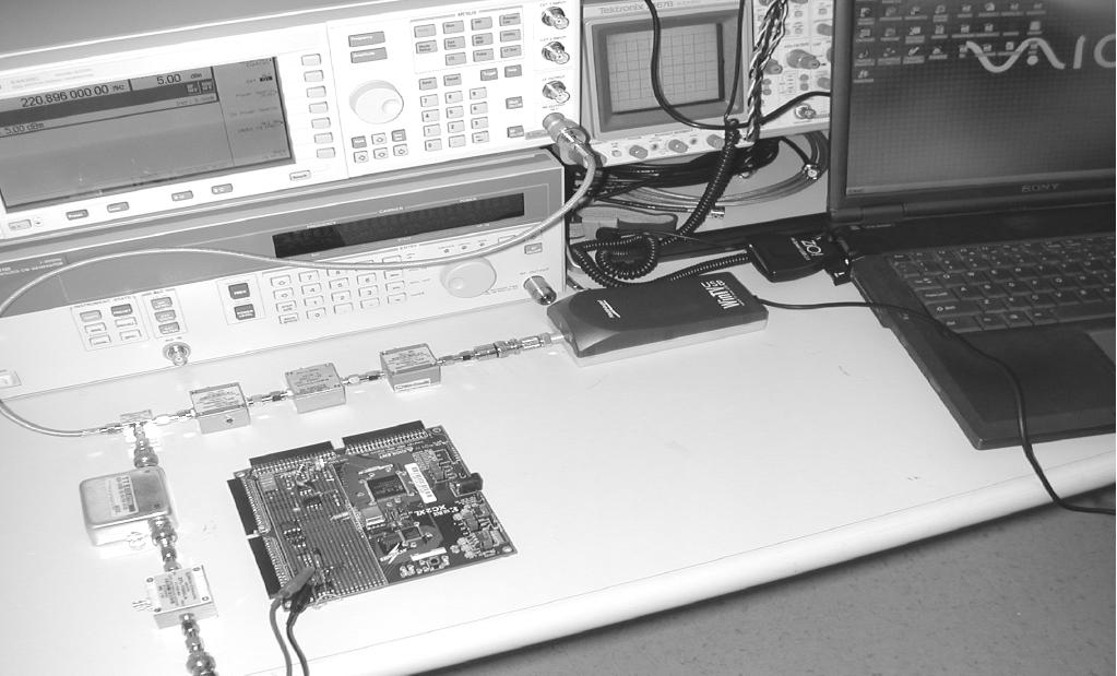
EXPERIMENTAL RESULTS
To demonstrate the feasibility of detecting LO leakage from radio receivers we built a prototype sensor from off the shelf components. The receiver under test was a Hauppauge computer based TV receiver. We attached a 10dB attenuator to the input port of the television to simulate a 10dB coupler. The output of the attenuator was connected to a broadband RF amplifier. The amplifier output was fed into the RF input of a mixer. The oscillator input of the mixer was driven by a signal generator whose frequency was set so that the LO leakage frequency of the TV receiver would get mixed down to a fixed IF band. An IF filter was chosen centered at 100KHz, with a 3dB bandwidth of 3KHz. The output of the IF stage was further amplified and sent to an envelope detector. The output of the enveloped detector gave us a DC signal whose level was proportional to the LO leakage power. This DC signal was fed to a comparator whose voltage threshold was set at the average of the DC level obtained when the LO leakage was present (indicating that the TV tuner was tuned to the corresponding channel) and the DC level obtained when the LO leakage was not present (indicating that the tuner was not tuned to the corresponding channel). The output of the comparator drove a light emitting diode (LED) to indicate the presence of the LO leakage at the specified channel. This setup is shown in Figure 4. The detection time of the circuit was very small, almost instantaneous to a human observer. We are currently working to replace the signal generator in the setup with a frequency synthesizer that will be able to scan all of the television channels and report the channel usage information to a cognitive radio.