Knowledge of the look direction is used to constrain the array response in the direction of the signal such that the signal arriving from the look direction is passed through the array processor undistorted. The array weights of the element space optimal beamformer are estimated by minimizing the mean out power subject to the look direction constraint. The processor maximizes the output signal to noise ratio by canceling all interference. A direction source is treated as interference if it is not in the look direction. This shows the importance of the accuracy of the look direction. An error occurs when the look direction is not the same as the desired signal direction. For this case, the processor treats the desired signal source as interference and attenuates it. The amount of attenuation depends on the power of the signal and the amount of error. A stronger signal is canceled more and a larger error causes more cancelation of the signal.
The solution to the look direction error, also known as the beam-pointing error, is to make the beam broader so that when the signal is not precisely in the direction where it should be (the look direction), its cancelation does not take place. The various methods of broadening the beam include multiple linear constraints and norm constraints. Norm constraints prohibit the main beam blowing out as is the case in the presence of pointing error. In the process of canceling a source close to the point constraint in the look direction, the array response gets increased in the direction opposite to the pointing error. It makes use of direction finding techniques combined with a reduced dimensional maximum likelihood formulation to accurately estimate the direction of the desired signal. The effectiveness of this scheme in mobile communications has been demonstrated using computer simulations.
In this section, the performance of the optimal element space processor and the beam space processor in the presence of beam-pointing error is compared. The comparison presented here indicates that beam space processors in general are more robust to pointing errors than elements space processors.
A detailed comparative study of the performance of the two processors in the presence of the signal direction error (SDE) is presented in Figure 21 to Figure 27. These figures show how the direction of the interference source, the number of elements in the array, and the uncorrelated noise power level affect the performance of the two processors as a function of the error in the signal direction. For all these figures, interference power is taken to be 20 dB more than signal power.
Figure 21 to Figure 24 show, respectively, the comparison of the output signal powers, the output uncorrelated noise powers, the power patterns, and the output SNRs of two processors when the assumed look direction is broadside to a ten-element linear array with half-wavelength spacing. The direction of the interference is 85° relative to the line of the array, and the uncorrelated noise power level is 20 dB below the signal level. The interference beamforming weights of the PIC processor are calculated using (6.91) and (6.92).
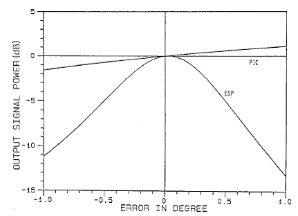
Figure 2.21 shows that the output signal powers of the two processors are the same in the absence of the SDE. As the SDE increases, the signal suppression by the ESP increases, and it suppresses more than 11 dB signal power in the presence of a 1° error in the signal direction. Note that the error in the signal direction is measured relative to the look direction and is assumed to be positive in the counterclockwise direction. Thus, −1° and 1° error, respectively, means that the signal direction is 89° and 91° relative to the line of the array. Furthermore, the line of the array, interference direction, and signal direction are in the same plane.
The signal suppression of the PIC processor is substantially less than that of the ESP. It reduces the output signal power less than 2 dB in comparison to 11 dB of the ESP when the error is −1° and increases the output signal power by about 1 dB when the error is 1°, in which case the ESP suppresses more than 13 dB of signal.

Figure 21 : Output signal power vs. the SDE for a ten-element linear array, PI = 100, σn^2 = 0.01, θI = 85°.
A comparison of the uncorrelated noise powers of the two processors is shown in Figure 22. This figure shows that there is no noticeable effect on the output uncorrelated noise power of the PIC processor due to the presence of the SDE. However, there is a significant increase in the uncorrelated noise output power of the ESP. A small SDE, of the order of 0.4°, causes an increase of the order of 20 dB in the uncorrelated noise output power.
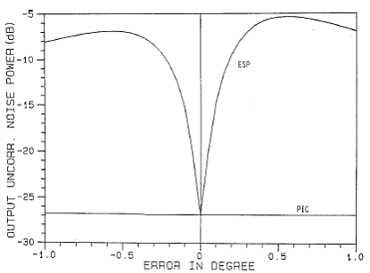
Figure 22 : Output uncorrelated noise power vs. the SDE for a ten-element linear array, PI = 100, σn^2 = 0.01, θI = 85°.
Figure 23 shows the power patterns of the two processors when the error is 1°. The reduced response in the signal direction and an increased response to the uncorrelated noise are clearly visible from the pattern of the ESP.
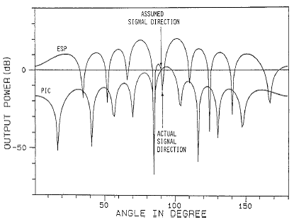
Figure 23 : Power pattern of a ten-element linear array when SDE = 1°, PI = 100, σn^2 = 0.01, θI = 85°.
Figure 24 compares the output SNRs of the two processors. The performance of the two processors is the same in the absence of errors. The effect of the SDE on the output SNR of the PIC is a slight reduction for a −1° error and a slight increase for a 1° error. However, the error causes a significant reduction in the output SNR of the ESP.
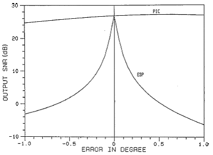
Figure 24 : Output SNR vs. the SDE for a ten-element linear array, PI = 100, σn^2 = 0.01, θI = 85°.
Figure 25 compares the output SNRs of the two processors when the interference direction is 25° relative to the line of the array. This figure demonstrates that the output SNR of the ESP in Figure 25 is reduced by more than 20 dB by 0.1° error in the signal direction. On the other hand, the effect of the SDE on the output SNR of the PIC is negligibly small. It should be noted that the constant ρ attains values of 0.99 and 0.48, respectively, for the scenarios of Figure 24 and Figure 25. A comparison of these figures shows how the direction of the interference affects the output SNR of the ESP for a given SDE. One observes that the performance of the ESP in a noise configuration with a higher value of ρ is poorer than that with a lower value of ρ.
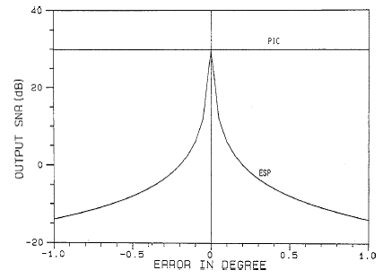
Figure 25 : Output SNR vs. the SDE for a ten-element linear array, PI = 100, σn^2 = 0.01, θI = 25°.
Figure 26 shows the output SNR plots of the two processors when the uncorrelated noise level is raised to that of the signal level. Other noise and array parameters are the same as in Figure 25. The effect of the raised uncorrelated noise level on the ESP in the presence of the SDE is that the processor becomes less sensitive to the error. The output SNR of the ESP in the presence of a 1° error is about 4 dB, in comparison to about 10 dB of the PIC processor. The output SNR of 10dB is the level achievable by the two processors in the absence of the error.
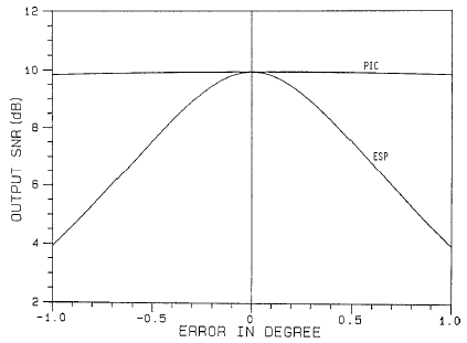
Figure 26 : Output SNR vs. the SDE for a ten-element linear array, PI = 100, σn^2 = 1, θI = 25°.
For a given uncorrelated noise level, the output SNRs of the two processors in the absence of errors can be increased by increasing the number of elements, as shown in Figure 27, where the number of elements of the linear array is increased from 10 to 20. Comparing Figure 27 with Figure 26, an increase of about 3 dB in the output SNRs of the two processors in the absence of SDE is noticeable. One also observes from the two figures that the ESP is more sensitive to the SDE in the presence of an array with a greater number of elements. With an array of 20 elements, the output SNR of the ESP in the presence of 1° SDE is about −4 dB, in comparison to 4 dB when the number of elements in the array is ten.
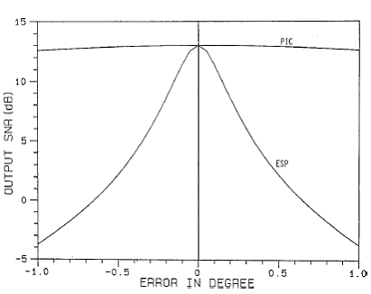
Figure 27 : Output SNR vs. the SDE for a 20-element linear array, PI = 100, σn^2 = 1, θI = 25°.
The above results show that in the absence of errors both processors produce identical results, whereas in the presence of look direction errors the beam space processor produces superior performance. The situation arises when the known direction of the signal is different from the actual direction. Now let us look at the reason for this difference in the performance of the two processors.
The weights of the processor are constrained with the known look direction. When the actual signal direction is different from the one used to constrain weights, the ESP cancels this signal as if it were interference close to the look direction. The beam space processor, on the other hand, is designed to have the main beam steered in the known look direction and the auxiliary beams are formed to have nulls in this direction. The response of the main beam does not alter much as one moves slightly away from the look direction, and thus the signal level in the main beam is not affected. Similarly, when a null of the auxiliary beams is placed in the known look direction, a very small amount of the signal leaks in the auxiliary beam due to a source very close to the null and thus the subtraction process does not affect the signal level in the main beam, yielding a very small signal cancelation in the beam space processing compared to the ESP.
Back To Contents .