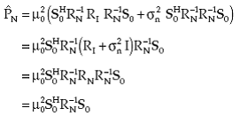
The null steering scheme described in 2.3 requires knowledge of the directions of interference sources, and the beamformer using the weights estimated by this scheme does not maximize the output SNR. The optimal beamforming method described in this section overcomes these limitations and maximizes the output SNR in the absence of errors. It should be noted that the optimal beamformer, also known as the minimum variance distortionless response (MVDR) beamformer, described in this section does not require knowledge of directions and power levels of interferences as well as the level of the background noise power to maximize the output SNR. It only requires the direction of the desired signal.
In this section, first we discuss an optimal beamformer with its weights without any constraints, and then study its performance in the presence of one interference and uncorrelated noise.
Unconstrained Beamformer
Let an L-dimensional complex vector w represent the weights of the beamformer shown in Figure 1 that maximize the output SNR. For an array that is not constrained, an expression for w is given by:
(4.1) |
where RN is the array correlation matrix of the noise alone, that is, it does not contain any signal arriving from the look direction (φ0,θ0) and μ0 is a constant.
Consider that the noise environment consists of the random noise of power σn^2 and a directional interference of power pI in nonlook direction. Assume that there is a source of power PS in the look direction, and that the interference and the signal are uncorrelated. For this case, the array correlation matrix R is given by
(4.2) |
The mean output power of the processor is given by
(4.3) |
|
(4.4) |
so
(4.5) |
|
(4.6) |
|
(4.7) |
Substituting for w :
(4.8) |
|
(4.9) |
|
(4.10) |
where RI is the correlation matrix of interference and
 |
(4.11) |
The total noise at the output is given by
(4.12) |
Substituting from (4.9) and (4.10), total noise becomes
 |
(4.13) |
Constrained Beamformer
Let the array weights be constrained to have a unit response in the look direction, that is,
(4.14) |
Thus, it follows from (4.1) that constant μ0 is given by
(4.15) |
Substituting this in (4.1) results in the following expression for the weight vector
 |
(4.16) |
Substituting for μ0 in (4.8), (4.9), (4.10) and (4.13) results in the following expressions for the output signal power, residual interference power, output uncorrelated noise power, and the total noise power of the constrained beamformer
(4.17) |
|
 |
(4.18) |
(4.19) |
|
(4.20) |
Note from (4.19) that β is the ratio of the uncorrelated noise power at the output of the constrained beamformer to the uncorrelated noise power at its input.
As the weights for the optimal beamformer discussed above are computed using noise alone matrix inverse (NAME), the processor with these weights is referred to as the NAME processor. It is also known as the maximum likelihood (ML) filter, as it finds the ML estimate of the power of the signal source, assuming all sources as interference. It should be noted RN may be not be invertible when the background noise is very small. In that case, it becomes a rank deficient matrix.
In practice when the estimate of the noise alone matrix is not available, the total array correlation matrix (signal plus noise) is used to estimate the weights and the processor is referred to as the SPNMI (signal-plus-noise matrix inverse) processor. An expression for the weights of the constrained processor for this case is given by
(4.21) |
These weights are the solution of the following optimization problem:
 |
(4.22) |
Thus, the processor weights are selected by minimizing the mean output power of the processor while maintaining unity response in the look direction. The constraint ensures that the signal passes through the processor undistorted. Therefore, the output signal power is the same as the look direction source power. The minimization process then minimizes the total noise including interference and the uncorrelated noise. The minimization of the total output noise while keeping the output signal constant is the same as maximizing the output SNR.
It should be noted that the weights of the NAMI processor and the SPNAMI processor are identical; and in the absence of errors, the processor performs identically in both cases. This fact can be proved as follows. The Matrix Inversion Lemma for an invertible matrix A and a vector x states that
 |
(4.23) |
since
|
(4.24) |
so
|
(4.25) |
and
|
(4.26) |
and
|
(4.27) |
Equations (4.21), (4.26), and (4.27) imply
(4.28) |
|
Thus,
|
(4.29) |
For more information about optimal beamformer you can click here.
Later output signal to noise ratio and array gain of optimal beamformer is discussed.
Also optimal beamformer in the presence of uncorrelated noise only and one directional interference is discussed.
Back To Contents .