Introduction
Software radio is the technique of getting code as close to the antenna as possible. It turns radio hardware problems into software problems. The fundamental characteristic of software radio is that software defines the transmitted waveforms, and software demodulates the received waveforms. This is in contrast to most radios in which the processing is done with either analog circuitry or analog circuitry combined with digital chips. GNU Radio is a free software toolkit for building software radios.
Software radio is a revolution in radio design due to its ability to create radios that change on the fly, creating new choices for users. At the baseline, software radios can do pretty much anything a traditional radio can do. The exciting part is the flexibility that software provides you. Instead of a bunch of fixed function gadgets, in the next few years we'll see a move to universal communication devices. Imagine a device that can morph into a cell phone and get you connectivity using GPRS, 802.11 Wi-Fi, 802.16 WiMax, a satellite hookup or the emerging standard of the day. You could determine your location using GPS, GLONASS or both.
Perhaps most exciting of all is the potential to build decentralized communication systems. If you look at today's systems, the vast majority are infrastructure-based. Broadcast radio and TV provide a one-way channel, are tightly regulated and the content is controlled by a handful of organizations. Cell phones are a great convenience, but the features your phone supports are determined by the operator's interests, not yours.
A centralized system limits the rate of innovation. We could take some lessons from the Internet and push the smarts out to the edges. Instead of cell phones being second-class citizens, usable only if infrastructure is in place and limited to the capabilities determined worthwhile by the operator, we could build smarter devices. These user-owned devices would generate the network. They'd create a mesh among themselves, negotiate for backhaul and be free to evolve new solutions, features and applications.
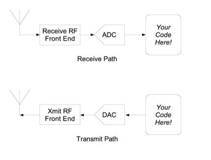
The Block Diagram
Figure 1, “Typical software radio block diagram” shows a typical block diagram for a software radio. To understand the software part of the radio, we first need to understand a bit about the associated hardware. Examining the receive path in the figure, we see an antenna, a mysterious RF front end, an analog-to-digital converter (ADC) and a bunch of code. The analog-to-digital converter is the bridge between the physical world of continuous analog signals and the world of discrete digital samples manipulated by software.
Figure 1. Typical software radio block diagram
ADCs have two primary characteristics, sampling rate and dynamic range. Sampling rate is the number of times per second that the ADC measures the analog signal. Dynamic range refers to the difference between the smallest and largest signal that can be distinguished; it's a function of the number of bits in the ADC's digital output and the design of the converter. For example, an 8-bit converter at most can represent 256 (28) signal levels, while a 16-bit converter represents up to 65,536 levels. Generally speaking, device physics and cost impose trade-offs between the sample rate and dynamic range.
Before we dive into the software, we need to talk about a bit of theory. In 1927, a Swedish-born physicist and electrical engineer named Harry Nyquist determined that to avoid aliasing when converting from analog to digital, the ADC sampling frequency must be at least twice the bandwidth of the signal of interest. Aliasing is what makes the wagon wheels look like they're going backward in the old westerns: the sampling rate of the movie camera is not fast enough to represent the position of the spokes unambiguously.
Assuming we're dealing with low pass signals - signals where the bandwidth of interest goes from 0 to fMAX, the Nyquist criterion states that our sampling frequency needs to be at least 2 * fMAX. But if our ADC runs at 20 MHz, how can we listen to broadcast FM radio at 92.1 MHz? The answer is the RF front end. The receive RF front end translates a range of frequencies appearing at its input to a lower range at its output. For example, we could imagine an RF front end that translated the signals occurring in the 90 - 100 MHz range down to the 0 - 10 MHz range.
Mostly, we can treat the RF front end as a black box with a single control, the center of the input range that's to be translated. As a concrete example, a cable modem tuner module that we've employed successfully has the following characteristics. It translates a 6 MHz chunk of the spectrum centered between about 50 MHz and 800 MHz down to an output range centered at 5.75 MHz. The center frequency of the output range is called the intermediate frequency, or IF.
In the simplest-thing-that-possibly-could-work category, the RF front end may be eliminated altogether. One GNU Radio experimenter has listened to AM and shortwave broadcasts by connecting a 100-foot piece of wire directly to his 20M sample/sec ADC.