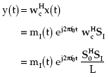
Let only a directional interference of power PI be present in direction (φI,θI). Let mI(t) and SI, respectively, denote the modulating function and the steering vector for the interference. The array signal vector for this case becomes
(2.11) |
The array output is obtained by taking the inner product of weight vector and the array signal vector. Thus,
 |
(2.12) |
The quantity (S0)H*S0/L determines the amount of interference allowed to filter through the processor and thus is the response of the processor in the interference direction. The amount of interference power at the output of a processor is given by (2.17). Thus in the presence of interference only, an expression for the mean output power of the conventional processor becomes
 |
(2.13) |
For a single source in the nonlook direction
(2.14) |
Substituting for RI and wc in (2.13),
(2.15) |
where
(2.16) |
and depends on the array geometry and the direction of the interference relative to the look direction.
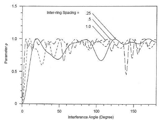
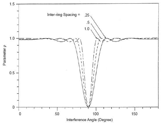
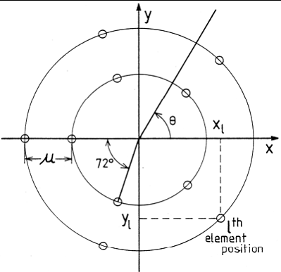
The effect of the interference direction on parameter ρ is shown in Figure 5 and Figure 6 for two types of arrays, planar and linear. The planar array consists of two rings of five elements each, as shown in Figure 7, whereas the linear array consists of ten equispaced elements.

Figure 5 : Parameter ρ vs. interference direction at three values of inter-ring spacing for the array geometry shown in
Figure 7

Figure 6 : Parameter ρ vs. interference direction for a ten-element linear array.
For the planar array, the signal and the interference directions are assumed to be in the plane of the array; the signal direction coincides with the x-axis. For the linear array, the signal is assumed to be broadside to the array. For both cases, the direction of the interference is measured relative to the x-axis.
Figure 5 and Figure 6, respectively, show the values of ρ for various interference directions at three values of inter-ring spacing μ and three values of inter-element spacing d. The parameters μ and d are expressed in terms of the wavelength of the narrowband sources. These figures show how ρ depends on the array geometry for given interference and signal directions.

Figure 7 : Structure of planar array.
Back to conventional beamformer.
Conventional beamformer when a source is in the look direction is discussed here.
Conventional beamformer in the presence of an environment consisting of uncorrelated noise is discussed here.
Signal to noise ratio (SNR) of a conventional beamformer is discussed here.
Back To Contents .